Game Boy cartridge dumping on a Raspberry Pi - Part 2
In Part 1 I covered the materials I got, now how I put all of them together.
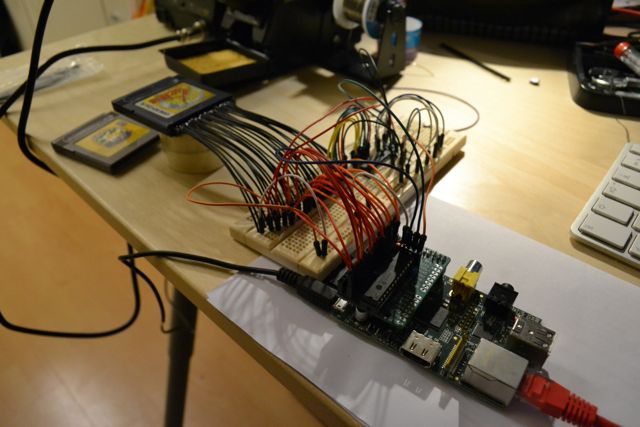
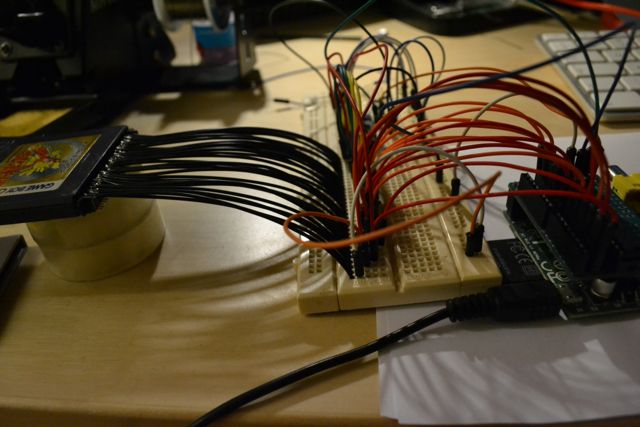
I had soldered my Slice of PI/O a while ago, so all I had to solder was wires for the cartridge header.
Well, that turned out more annoying than I expected. The area to solder on is really small and any overflow could connect two adjacent pins, leading to data corruption or worse. I had a hard time keeping all wires in place, especially when plugging the other ends into a breadboard. The wires are rather short and stiff, I had to put the cartridges on something to stop the contacts from breaking under the weight.
Hooking up was relatively straightforward, though I skipped most of the resistors InsideGadgets’ guide says are not strictly necessary. The MCP23017 on the Slice of PI/O (which I will refer to by its I^2 C address, 0x20), got hooked up to the 16 input pins of the cartridge header. I connected the A-side of the second MCP23017 (0x21) to the cartridge’s output pins, its B0 to the WR pin and B1 to RD.
After booting the Pi, both IO expanders showed up in i2cdetect -y 1 (1 because I have a 2nd revision Pi, if you have an older one, use 0). Poking around with i2cget and i2cset to find the obligatory header bytes (check TheNintendoGameboy.pdf to see what the header looks like), I discovered I had to set the lower 8 bits of the address on bank B of 0x20. Confusingly, I had to set the 8 higher bits on bank A, but in reverse. The byte it read, so on bank A of 0x21, was also reversed.
I managed to read ROM bank 0 successfully. After around 4 hours of debugging why I got ROM bank 33 when trying to read bank 1, I figured out the bank B pins of 0x21 (which connected RD and WR) were also reversed.
I haven’t figured out why, but compared to the schematic on this post (which inspired the Slice of PI/O), 0x21’s GBP0 up to GBP7 are definitely ordered in reverse.
The code
I have included the code I used to successfully dump Pokémon Yellow and Gold (both the Japanese editions). The code is written assuming the memory bank controller in the cartridge is of type MBC3 and that it has 64 ROM banks, as that is what both these cartridges have and I don’t have any others available to test. If you’re trying to use this but have a different number of ROM banks (check byte 0x0148 of the first bank and look it up in the PDF), you should be able to just change the number at the end. If your MBC is not of type MBC3 (check byte 0x0147), it will take some more changes to get this to work, as some require different methods of selecting the ROM bank.
The code reads all ROM banks into separate files, so gold0.gbc upto gold63.gbc. To create a playable ROM file out of this, I used the command:
for i in `seq 0 63`; do cat gold$i.gbc >> gold.gbc; done
I don’t know how many of the time.sleep()s are actually necessary, but without them I had some cases of corrupted data. The code takes 13 minutes to dump the complete game (for a 1MB game, that means I’m slower than the SNES dumping I mentioned in part 1…). Removing the sleeps does not speed it up much, the blocking reads and writes are the culprit. I might look at increasing the frequency i2c-dev uses, but I’m afraid that is going to require recompiling the kernel.
#! /usr/bin/python

# Read a Game Boy/Game Boy Color cartridge connected to two MCP23017 IO expanders.
# By Thijs Alkemade, 2013. Based on the script by Nathan Chantrell.
# GNU GPL V3

import smbus
import sys
import getopt
import time

def bytereverse(x):
        return int('{:08b}'.format(x)[::-1], 2)

f = None

# For revision 2 Raspberry Pi, change to bus = smbus.SMBus(0) for revision 1.
bus = smbus.SMBus(1)

address0 = 0x20
address1 = 0x21
bus.write_byte_data(address0,0x00,0x00) # Set all of bank A of 0x20 to outputs
bus.write_byte_data(address0,0x01,0x00) # Set all of bank B of 0x20 to outputs
bus.write_byte_data(address1,0x00,0xff) # Set all of bank A of 0x21 to inputs
bus.write_byte_data(address1,0x01,0x00) # Set all of bank B of 0x21 to outputs

def write(address):
    bus.write_byte_data(address0,0x13,address & 0xff)
    bus.write_byte_data(address0,0x12,bytereverse((address >> 8) & 0xff))

# Set ~RD and WR.
bus.write_byte_data(address1,0x13,bytereverse(0x02))

def read(start, end):
    for read_address in range(start, end):
        write(read_address)
        time.sleep(0.0001)

        val = bytereverse(bus.read_byte_data(address1,0x12))

        if (read_address & 0xff == 0x00):
                sys.stdout.write(".")
                sys.stdout.flush()
        f.write("%c" % val)

def select(bank):
    global f
    f = open("gold%d.gbc" % bank, 'w')
    sys.stdout.write("\n%d: " % bank)
    write(0x2100)
    time.sleep(0.001)
    bus.write_byte_data(address1,0x00,0x00)
    time.sleep(0.001)
    bus.write_byte_data(address1,0x12,bytereverse(bank))
    time.sleep(0.001)

    bus.write_byte_data(address1,0x13,bytereverse(0x01))
    time.sleep(0.001)
    bus.write_byte_data(address1,0x13,bytereverse(0x02))
    time.sleep(0.001)
    bus.write_byte_data(address1,0x12,0x00)
    time.sleep(0.001)
    bus.write_byte_data(address1,0x00,0xff)

    time.sleep(0.001)

select(0)

read(0x0000, 0x4000)


for bank in range(1, 64):
    select(bank)
    read(0x4000, 0x8000)
The next challenge: hacking a Game Boy emulator to use the cartridge directly. To be continued!
Recent posts
- The Wrong Number Attack
- Common DH groups
- Out with octopress, in with Hakyll
- Validate the encoding before passing strings to libcurl or glibc
- Multi-end to multi-end encryption
Copyright © 2024 - Thijs Alkemade
Site proudly generated by Hakyll.